
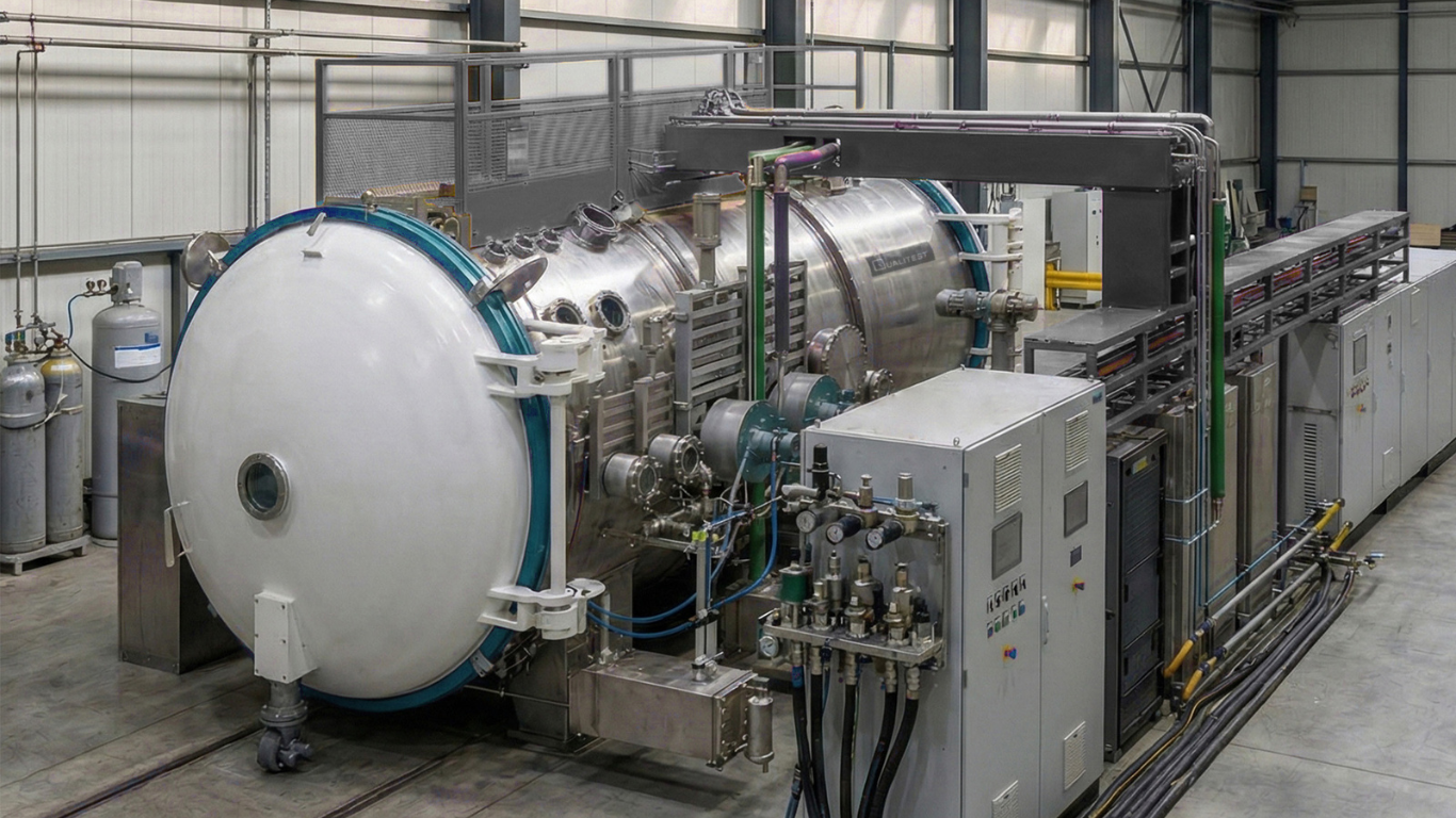
Aerospace engineering faces its most significant hurdle during the transition from a laboratory environment to the harsh vacuum of space. Thermal vacuum (TVAC) testing simulates the low pressure and controlled thermal loading of orbital environments to uncover vacuum-dependent and temperature-driven issues before hardware deployment. Performance specifications—such as ultimate pressure and thermal ramp rates—are critical, yet a common failure point in test planning is actually the physical envelope.
- Why Envelope Planning Matters in Thermal Vacuum (TVAC) Testing
- Define the True “Test Article”: Hardware + Fixture + Instrumentation
- The Core Sizing Drivers for a TVAC Chamber Envelope
- Fixture Planning: Making Setup Repeatable Across Runs
- Cabling and Feedthrough Strategy: Avoiding Bottlenecks
- Instrumentation Density: Planning for Sensors and Access
- Sizing by Test Type: Thermal Cycling vs. Thermal Balance
- Practical Envelope Planning Workflow
- Common Envelope Planning Mistakes
- Compare TVAC Chamber Options on WorldofTest
A successful test campaign requires more than just fitting the satellite or subsystem into the cylinder. In practice, fixtures, sensors, cable routing, and feedthrough planning consume significantly more space than the test article itself. Sizing a TVAC Chamber without accounting for these “setup overheads” leads to compromised data, thermal shorts, and increased risk during integration. This guide explains how to size your system to real-world setup needs so that every run remains repeatable and scientifically valid. Once you have defined your spatial constraints, you can explore TVAC chamber options on WorldofTest to compare scales and capabilities.
Why Envelope Planning Matters in Thermal Vacuum (TVAC) Testing
Envelope planning is the process of mapping out the physical volume required for the entire test setup, not just the hardware being tested. In the vacuum of space, the physics of heat transfer shifts fundamentally. Convection is non-existent, leaving radiation and conduction as the dominant modes of thermal exchange. Because of this, the boundary hardware used to control temperature—such as cold plates, heat sinks, and heater cages—must be positioned with precision.
These boundary elements are not just accessories; they are part of the “setup volume.” If a Thermal Vacuum (TVAC) system is too small, these elements are often crowded together, leading to unintended thermal gradients or “thermal shorts” where heat leaks through structural supports. Furthermore, repeatability depends on a stable environment. If a setup is so cramped that cable routing and sensor placement change between runs due to space constraints, the data becomes difficult to compare, complicating the qualification process.
Define the True “Test Article”: Hardware + Fixture + Instrumentation
One of the most frequent mistakes in procurement is providing dimensions based solely on the Flight Model (FM) or Engineering Model (EM). In a professional test lab, the “test article” is a much larger assembly that includes:
- Mounting Fixtures and Standoffs: These provide the mechanical interface to the chamber and often require specific heights to align the hardware with thermal windows or sensors.
- Sensor Harnesses: High-fidelity tests often require hundreds of thermocouples, RTDs, strain gauges, and pressure transducers. These bundles take up significant volume and require dedicated routing paths.
- Cable Bundles and Connectors: Power and data lines must transition from the hardware to the feedthrough interfaces on the chamber wall.
- Heat Sink and Cold Plate Surfaces: These are the primary interfaces for thermal control and usually extend beyond the footprint of the actual test piece.
Chamber sizing should always start from the dimensions of the full, assembled configuration in its “test-ready” state. If you only size for the satellite, you may find yourself without enough room to even turn a wrench during installation.
The Core Sizing Drivers for a TVAC Chamber Envelope
When evaluating the internal dimensions of a TVAC Chamber, engineers must look beyond the simple diameter and length. Several practical drivers dictate the minimum functional envelope:
- Radiation Path Clearance: To ensure uniform thermal loading, there must be adequate clearance between the test article and the thermal shrouds. If the hardware is too close to a shroud, “hot spots” or “cold spots” can occur, distorting the thermal balance.
- Fixture Footprint: The structural supports required to hold a 50kg instrument are often wider and taller than the instrument itself. These supports must also be compatible with the internal rails or mounting plates of the chamber.
- Thermal Boundary Hardware: Heater cages or IR lamps require specific “stand-off” distances to prevent scorching or uneven heating. Cold plates similarly require space for fluid lines and insulation.
- Cable Routing and Bend Radius: High-speed data cables and heavy power lines have a minimum bend radius. Forcing these cables into tight corners in a small TVAC system can cause signal degradation or mechanical failure of the connectors.
- Feedthrough Layout: The number and location of feedthroughs dictate how cables move from the article to the chamber wall. If the envelope is too tight, you may not be able to reach the connectors once the hardware is installed.
- Contamination Control: For sensitive optical or scientific instruments, specific spacing is required to ensure that outgassing from fixtures doesn’t condense on critical surfaces.
Fixture Planning: Making Setup Repeatable Across Runs
Repeatability is the hallmark of professional Thermal Vacuum (TVAC) testing. If you are running a series of qualification tests, the mechanical and thermal interfaces must remain identical across every run. This is only possible if the fixture is designed for stability and consistent placement.


Fixture design should focus on defined thermal interface surfaces and consistent mounting points. Many labs use modular fixtures that can be adjusted for different components while maintaining the same “datum” points within the chamber. When the envelope is properly planned, these fixtures can be rolled in and out on a rail system, ensuring that the hardware is in the exact same spot every time, which reduces the number of variables during data analysis.
Cabling and Feedthrough Strategy: Avoiding Bottlenecks
Cabling is often the “hidden” volume in a test setup. A high-density instrumentation plan can result in a harness thicker than a human arm. If the TVAC Chamber envelope does not account for this volume, the cables can end up draped over thermal shrouds or blocking radiation paths.
Feedthrough planning must happen early in the sizing process. You should count your required channels—including power, high-speed data, and sensors—and then add a 20% growth margin. It is far easier to buy a chamber with extra feedthrough ports than to modify a vacuum vessel later.
Cabling Checklist:
- Channel Count: Estimate your total leads and add a margin for program growth or troubleshooting sensors.
- Connector Labeling: Ensure the setup allows for clear labeling so that cables aren’t crossed in a cramped space.
- Routing Map: Define specific “stay-out” zones where cables should not pass, such as near high-heat IR lamps.
- Thermal Isolation: Use tie-downs and harness guides to ensure cables don’t create unintended conduction paths between the test article and the chamber walls.
Instrumentation Density: Planning for Sensors and Access
During the qualification phase of a space program, you will almost always need more sensors than you initially anticipated. If a thermal model doesn’t match the test data, the first response is usually to add more thermocouples to investigate the discrepancy.
The TVAC Chamber must have enough internal mounting points and cable tray guides to accommodate this density. Furthermore, access is a major sizing driver. If a sensor fails during the “pump-down” phase or during pre-test checks, can a technician reach into the chamber to replace it without removing the entire test article? Proper envelope planning includes “human-scale” access for sensor maintenance and final inspections.
Sizing by Test Type: Thermal Cycling vs. Thermal Balance
The type of test you perform will also dictate your envelope needs:
- Thermal Cycling: The priority here is ramp behavior and hitting setpoints. The envelope needs to support the rapid movement of heat, which often means more space for heater cages or high-flow cold plates.
- Thermal Balance: These tests are much more sensitive. They require extremely stable boundary conditions and comparable runs. The setup consistency is paramount, meaning the envelope must be large enough to ensure that the hardware is perfectly isolated from the chamber’s own thermal mass.
Practical Envelope Planning Workflow
To ensure you choose the right system scale, follow this step-by-step sequence:
- Define the Largest Configuration: Model the hardware, the fixture, and the full harness bundle together.
- Map the Sensor Plan: Determine your channel count and where the wires will logically exit the assembly.
- Define Cable Routing: Trace the path from the hardware to the expected feedthrough locations, respecting bend radii.
- Layout Thermal Hardware: Place your cold plates, heater cages, or solar simulators to ensure they have the required clearance.
- Validate Access: Simulate the installation process. Is there room for tooling, lifting eyes, and technician hands?
- Confirm Cleanliness Needs: If the part is sensitive, ensure there is enough volume for bake-out baffles or contamination monitors.
- Choose the Chamber: Finally, select a system that supports this configuration with room to spare for future, larger projects.
Common Envelope Planning Mistakes
- Sizing Only to Hardware Dimensions: This is the #1 cause of test delays. Always add a 30-50% volume buffer for setup overhead.
- Underestimating Harness Volume: Cables are not zero-width; in a vacuum, they must be managed carefully to avoid overheating.
- No Troubleshooting Margin: If you can’t add five more sensors because there’s no room, you can’t solve anomalies.
- Thermal Shorts: Forgetting that a fixture touching a cold wall will act as a giant heat sink, ruining the thermal model.
- Poor Installation Access: Rushed setups in cramped spaces lead to broken connectors and expensive “re-runs.”
Compare TVAC Chamber Options on WorldofTest
Selecting a chamber is a long-term investment for any aerospace lab. Once you have defined your requirements for fixtures, cabling, and instrumentation density, the next step is to evaluate systems that can support your mission. We recommend a “requirements-first” selection mindset where the physical envelope is treated with as much importance as the vacuum level.
We invite you to explore Thermal Vacuum (TVAC) test chambers on WorldofTest and request a quotation based on your specific fixture, cabling, and instrumentation requirements. By matching the scale of your system to the reality of your test setup, you protect the repeatability of your data and speed up your program execution.
In conclusion, correct sizing is about the full setup, not just the test article. Diligent envelope planning reduces the risk of thermal shorts, ensures measurement accuracy, and provides the flexibility needed to solve the unexpected challenges of space simulation.